Instructions
- Enter the desired Stop Value in the Stop At input section(0–255).
- Select the Update Frequency in Hz, it is simply counting speed(can be changed anytime).
- Click View Circuit Diagram to see how the 8051 and LEDs are connected in logic diagram and in block diagram.
- Click View Assembly Code to analyse the assembly code used for this experiment.
- Now according to your analysis write your code in the Assembly Code Editor.
- Click Check Code to verify your program against the given code.
- If correct → a success message will appear and Start Simulation will be enabled.
- If incorrect → you’ll be asked to review and correct your program.
- (Optional) You can directly copy code into editor by clicking on Use Code in View Assembly code popup.
- After validation, click Start Simulation to run the simulation.
- Observe the led pattern and Count. You can change Update frequency if you want to vary the counting speed.
- If you want to save your program, click Download Code. It will be stored as
binary_counter.asm. - Click Reset Simulation to stop the simulation, clear the editor, and reset everything to default.
Tip: Click "View Assembly Code" then "Use Code" to copy it into the editor.
Components used in this experiment: 8051 Microcontroller, LEDs
Flow of circuit: 8051 Microcontroller ⟶ LEDs
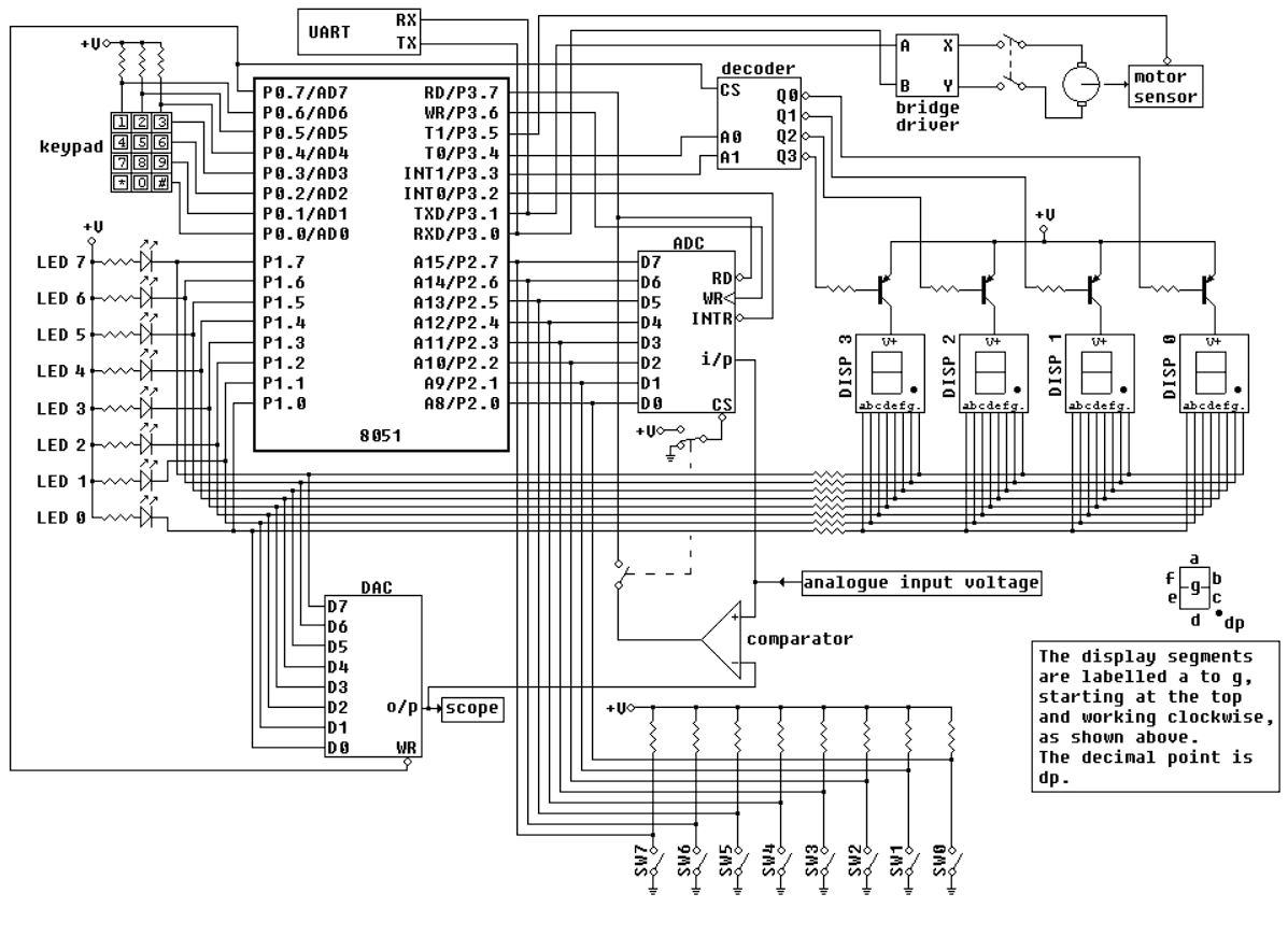
Figure : Logic Diagram
Binary Counter Assembly Code
Please enter a valid Stop Value (0–255) to see sample code.
Count:
0 (00000000)