Instructions
- Click View Circuit Diagram to see how the 8051 and LEDs are connected in logic diagram and in block diagram.
- Click View Assembly Code to analyse the assembly code used for this experiment.
- Now according to your analysis write your code in the Assembly Code Editor.
- Click Check Code to verify your program against the given code.
- If correct → a success message will appear and Start Simulation will be enabled.
- If incorrect → you’ll be asked to review and correct your program.
- (Optional) You can directly copy code into editor by clicking on Use Code in View Assembly code popup.
- After validation, move the Analog Input slider and click Convert to convert the analog input to digital output.
- Observe the equivalent output on the 7 segment displays and. You can move the slider and click on convert if you want to convert for other values.
- If you want to save your program, click Download Code. It will be stored as
adc_code.asm. - Click Reset to clear the editor, and reset everything to default.
Assembly Code Editor
Tip: Click "View Assembly Code" then "Use Code" to copy it into the editor.
Components used in this experiment: 8051 Microcontroller, ADC, DISP1, DISP0.
Flow of circuit: Analog Input Voltage ⟶ ADC ⟶ 8051 Microcontroller ⟶ DISP1&DISP0.
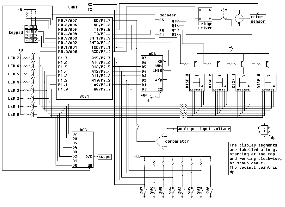
Figure : Logic Diagram
ADC Code
Analog Input
0V1V2V3V4V5V